Finding a Perimeter Wire Break – A bit of background
One of my clients had a wire break yesterday and asked me what was the best approach to finding it.
He had a multimeter but didn’t have a wire break detector so I put together a quick ‘How To’ to help explain the approach and sent it to him.
Today, I came home and I had a wire break so I thought I might as well publish what I had put together and see if it helped people and if anyone else had any other tips.
Prevention is better than cure
What really annoyed me about my wire break is that a couple of days ago, I noticed a perimeter wire that was on the surface and had all the insulation stripped off.
This is the second mower to be installed in the area and I replaced the perimeter wire when I installed the new mower as the old one wasn’t done particularly well. As the old one was down for a couple of years it was difficult to pull it up so a lot of it was left in the ground.
I thought the wire I saw was just the remnants of the old wire and ignored it…how wrong I was.
So the moral of the story is, if you see some wire visible check it and if it is the perimeter wire, bury it or peg it securely – don’t just ignore it like I did!
Useful tools
You could just assume it will never happen to you but if it does, it’s useful to have a few tools around:
1. A multimeter

Always useful around the house anyway – can be picked up for less than £10 from amazon etc. If it has a audible continuity checker even better.
2. A long piece of wire (your test wire)

Preferably long enough to reach from the base to the perimeter wire furthest from the base – check that there is minimal resistance (a few ohms) from end to end using your new multimeter.
3. Some spare connectors and some spare wire to repair the break.


For connectors you can use 3M 314 gel filled connectors, these are quick and easy. Available from amazon but make sure that you get real ones not cheap copies.
Alternatively
Use solder filled connectors which require a heat gun to heat them up but give a better longer lasting joint. Again get good quality ones.
The other thing is to know your cable i.e. if you joins in your cable already, make a note of there they are, if you have wire going to an island/ flowerbed, make a note of where they are. I normally now take photos of joins, recalls to wire and wires to islands and include them in an installation summary along with the original settings.
Step 1 – Confirm it is a wire break
Different mowers will signify a break in different ways, for Ambrogios, the led on the base goes red and the mower says ‘No Signal’.
The first thing to do is confirm it is a break in the wire:
- Check that the perimeter wire is connected to the base…sounds obvious but it is possible to move the base slightly and disconnect one the wires
- Check that the problem is with the wire – take the perimeter wire out of the connectors on the base and measure the resistance between the 2 ends…it should be about 1 ohm per 100m of wire but if you have joins in the wire it could be double that. If there is a complete break then the resistance would be off the scale, resistances of kilo ohms (1000 ohms +) would indicate that the wire has probably been compromised i.e. some of the strands in the wire are not connected.
- If the resistance looks ok, then connect a few meters of wire between the base terminals, this should complete the circuit and turn the led green, if not then the problem could be the transmitter.
Step 2 – Walk the perimeter wire
Probably about 80% of breaks are found by a pure manual inspection of the wire.
Look for recently dug holes, wire on the surface etc. and inspect them closely. If the break is caused by an animal, often you will see the hole with the 2 ends of the wire visible.
If you have had any work done recently in the garden then this is another place to look.
Beware!
If you haven’t used the mower for a while e.g. over the winter, don’t assume that you have just one break. If you find one, fix it temporarily and then retest.
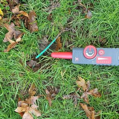
Step 4 – Use a wire break detector
A wire break detector is a transmitter that sends a signal down the wire and then a receiver that picks up the signal.
You connect one terminal of the signal generator to one end of the perimeter wire and ground the other connector.
In theory you can follow the wire around until the signal stops and that is where the break is. In practice it is often not as easy as that as the signal can drop a bit instead of stopping if it is a partial break or a connector that is of high resistance or you can pick up the signal from another piece of the perimeter wire that is close.
The trick is to generate as little signal as possible and keep turning it up. Once you have found where you think the break is, try from the other end of the perimeter wire and see if you end up in the same position.
There are a number of break detectors on the market, the price of them usually reflects the quality and how close you need to be to the wire to pick up the signal.
MS6812 – less than £30
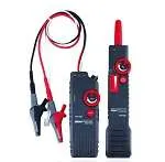
NF-820 – less than £70
MS6818 – less than £200
With the cheaper ones, you may actually need to expose the cable and touch it in order to test the signal, with the more expensive ones you can be a couple of meters away from the wire with it buried and it will still pick it up. I’ve added some links but shop around as you will see the same model rebadged by different resellers at greatly varying prices.
If you don’t have a break detector to hand, there are some ‘free’ alternatives which sometimes work:
- Some people have had luck with using the base and an AM radio, the results vary according to the age of the base technology and the make – with one end of the perimeter wire is attached to the base, put the aerial of an AM radio near the wire and follow it around. This video is for a Husqvarna but is the same principle.
- You can make a signal generator using an old petrol mower to generate noise and use a radio to follow it.
Step 5 – The non-technical way or as a last resort
If other methods have failed then sometimes there is no other way than trying to narrow down the break into a section of wire and then inspecting it closely. You will need your multimeter & your test wire.
Sample layout

Lets start with a layout. For Ambrogios, the wire coming into the front of the base goes to the red terminal and the one coming into the back is black (hence the colouring)
Narrow it down
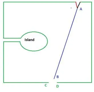
Find a point that is half way around the wire i.e. point C/D. If you already have a join in the wire start there as you can just replace the connector.
Remove the existing join/ cut the wire , join the 2 wires going into the base to one end of your test wire. Measure the resistance from B to C and B to D. You would expect the side that has a high (off the scale) resistance to be the side of the break i.e. if B to D has high resistance then the wire between D and A has the break. Now you can walk D to A and look more closely to see any breaks or use the break detector again – the shorter the wire, the more effective they are.
Still haven’t found it?

So you’ve narrowed it down to being between A and D but still haven’t found it?
Temporarily join C & D back together. Find another join halfway between A & D (E/F).
Now test the resistance from the base to the new point i.e. B to E and B to F.
If there is high resistance between B and E then the break is between the base and E and if you test B to F, it should be low resistance.
If it is high resistance between B and F, the break must be between F and D.
You can always use your test wire to test between D and F to make sure.
You can keep narrowing it down but remember, the more joins you have in a wire, the more potential points of failure there are.
Have an island?
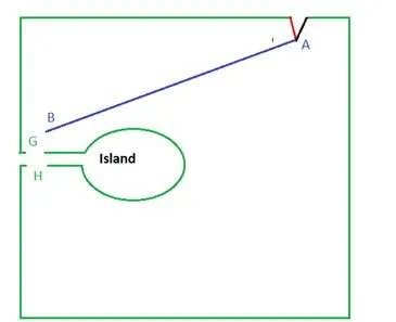
If you think that the break may be in an island i.e. the perimeter wire has been put around an obstacle (flower bed) in your garden then you can use the same approach.
First test if the island is ok i.e. test the resistance from G to H if it is low then the island is ok but you can then measure the resistance between B and G and B and H to identify which side of wire has a break.